

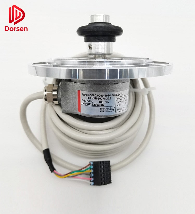
The encoder is the primary feedback device in modern elevator drive systems. It converts shaft rotation into electrical signals that the controller uses for speed regulation, position tracking, and floor leveling. An incorrectly specified encoder — wrong resolution, voltage, connector pinout, or mounting geometry — does not merely cause inconvenience. It produces speed instability, cumulative floor errors, repeated drive faults, and unnecessary repeat service calls.
This guide covers encoder classification, selection parameters, replacement procedures, commissioning requirements, and procurement best practices for maintenance contractors and parts distributors sourcing OEM-compatible replacements.
1. Encoder Fundamentals in Elevator Applications
1.1 Role in the Drive System
In a traction elevator, the encoder mounts on the motor shaft (or a dedicated feedback shaft coupled to the traction machine). As the motor rotates, the encoder generates pulses or analog signals proportional to angular displacement. The inverter compares this feedback against the commanded speed profile and adjusts motor torque accordingly.
For floor positioning, the controller counts encoder pulses (or reads absolute position) between deceleration points and leveling zones. Any error in pulse count — from signal loss, resolution mismatch, or mechanical slip — translates directly into mis-leveling at the landing.
Door operators use smaller encoders or Hall-effect feedback devices for position control during open and close strokes. The selection principles are similar but operating environments differ: higher vibration, more frequent direction reversals, and exposure to door track debris.
1.2 Encoder Types Used in Elevators
| Type | Output Signal | Power-On Position | Typical Application |
|---|---|---|---|
| Incremental | A/B/Z square-wave channels | Requires homing or shaft learn | Geared traction, older VVVF drives |
| Absolute (multi-turn) | Serial or parallel position word | Available immediately | Modern MRL, some regenerative drives |
| Sin/Cos (analog) | Sine and cosine waveforms | Requires index or reference | Permanent-magnet synchronous motors |
| Tachometer (legacy) | DC voltage proportional to speed | N/A — speed only | Older systems being retrofitted |
Incremental encoders are the most common replacement category. They output two phase-shifted channels (A and B) for direction discrimination, plus an index pulse (Z) once per revolution for reference. Resolution is expressed in pulses per revolution (PPR) — common values include 1024, 2048, 4096, 8192, and 10000.
Sin/Cos encoders provide continuous analog feedback with effectively infinite resolution when interpolated by the drive. They are standard on permanent-magnet gearless machines from KONE, Otis, Schindler, and Mitsubishi. Replacement requires exact voltage and phase matching — not just PPR equivalence.
Absolute encoders store position in non-volatile memory. After power loss, the controller reads current position without a shaft-learn procedure. Retrofitting an incremental encoder onto an absolute system (or vice versa) is generally not feasible without controller modification.
2. Key Selection Parameters
2.1 Resolution (PPR)
Resolution must match the drive’s expected feedback density. Installing a lower-resolution encoder on a system calibrated for 8192 PPR causes coarser position control and may prevent accurate leveling. Installing higher resolution without drive reprogramming may cause speed calculation errors.
| Symptom of resolution mismatch | Likely cause |
|---|---|
| Consistent floor offset (same direction every trip) | PPR setting in drive does not match encoder |
| Speed hunting at constant command | Pulse frequency outside drive input range |
| Drive reports “encoder fault” at startup | Zero pulse count or wrong channel assignment |
Always cross-reference the original nameplate PPR against the inverter parameter list before ordering.
2.2 Shaft Diameter and Mounting
Encoder mounting falls into three common categories:
- Flange mount — bolt circle on encoder face attaches to motor end bracket
- Sleeve / hollow shaft — encoder slides over motor shaft extension, secured with set screw or clamp
- Coupling mount — flexible coupling connects encoder shaft to motor shaft (allows minor misalignment)
Shaft diameter tolerance is critical. A 10 mm encoder on a 9.98 mm shaft may work with a set screw; a 10 mm bore on a 10.2 mm shaft will not seat correctly and causes eccentric rotation — a direct source of signal jitter.
2.3 Supply Voltage and Output Levels
| Voltage class | Common use | Notes |
|---|---|---|
| 5 V DC (TTL/HTL) | Most incremental encoders | Short cable runs; sensitive to noise |
| 12 V DC | Industrial incremental | Better noise immunity on longer cables |
| 24 V DC | Some door operator feedback | Verify drive input compatibility |
| 1 Vpp Sin/Cos | PM motor drives | Analog — requires shielded cable |
Supplying 12 V to a 5 V encoder destroys the internal electronics. Verify voltage on the nameplate and on the drive terminal strip before connecting a replacement.
2.4 Connector Type and Pin Definition
Elevator encoders use proprietary connectors: 6-pin, 8-pin, 12-pin circular connectors, or direct wire pigtails. Pin assignments for power (+V, 0V), channel A, channel B, index Z, and shield drain vary by manufacturer.
Rule: Never assume pin compatibility between brands. A KONE-compatible encoder connector wired like an Otis unit will produce reversed direction or no signal. Request a pinout diagram from the supplier or photograph the original wiring before disconnecting.
2.5 Brand and Model Compatibility
OEM-compatible replacements are designed to match the form factor, electrical characteristics, and mounting geometry of original assemblies. Common compatibility families include:
- KONE (KM series drives, MX machine encoders)
- OTIS (Gen2, SkyRise feedback modules)
- Schindler (BIOS, PORT encoders)
- Mitsubishi (NEXIEZ, ELENESSA)
- Hitachi, ThyssenKrupp/TKE, Fujitec
Model numbers on the nameplate (e.g., RE-0444, XAA, KM-series) are the primary matching reference — not the elevator model name.
3. Pre-Replacement Diagnostic Checklist
Before ordering a replacement encoder, confirm the encoder itself has failed. A significant share of “encoder fault” callbacks trace to other causes:
| Check | Method | Pass criteria |
|---|---|---|
| Wiring continuity | Ohmmeter on cable (power off) | No open circuits on A, B, +V, 0V |
| Shield termination | Visual inspection at drive end | Shield drain connected per drive manual |
| Coupling integrity | Manual rotation of motor shaft | Encoder rotates without slip or free play |
| Rope slip | Chalk mark test on sheave | < 5 mm drift per floor |
| Sin/Cos voltage | Voltmeter on inspection run | 1.45–1.55 V per channel, balanced |
If diagnostics point to wiring or mechanical slip, replacing the encoder will not resolve the fault. See our companion article on encoder troubleshooting for the full field sequence.
4. Replacement Procedure
4.1 Lockout and Documentation
- Apply lockout/tagout to main disconnect and verify zero voltage at controller terminals
- Photograph original wiring — connector orientation, shield routing, cable tie positions
- Record encoder nameplate data: model, PPR, voltage, serial number
- Note motor and drive model numbers for cross-reference
4.2 Physical Removal and Installation
- Disconnect encoder cable at the drive end first, then at the encoder
- Remove coupling or set screws; extract encoder without damaging the motor shaft surface
- Inspect shaft for scoring, burrs, or corrosion — dress minor defects before installing new unit
- Install replacement encoder; torque set screws to manufacturer specification (typically 2–4 N·m)
- Verify coupling alignment if applicable — misalignment causes bearing wear and signal noise within months
4.3 Wiring and Shielding
- Route encoder cable separately from power and brake-resistor wiring (minimum 100 mm separation where possible)
- Terminate cable shield at the drive end per manufacturer grounding scheme
- Use original connector or supplier-provided equivalent — do not leave bare wire splices in the machine room
- Confirm correct channel assignment (A/B swap causes reversed direction)
5. Post-Installation Commissioning
Skipping commissioning is the most common cause of faults immediately after encoder replacement.
| Step | Action | Purpose |
|---|---|---|
| 1 | Power up and verify encoder supply voltage at terminals | Confirms wiring before motion |
| 2 | Run direction test in inspection mode | Detects reversed A/B channels |
| 3 | Perform zero calibration / offset adjustment | Aligns electrical zero to mechanical reference |
| 4 | Execute shaft learn or position teach | Rebuilds floor position table |
| 5 | Test express run and leveling at every floor | Confirms resolution and position accuracy |
| 6 | Run loaded test (50% capacity minimum) | Reveals slip-related errors invisible at empty car |
Acceptance criterion used in many service contracts: floor leveling within ±5 mm at every landing after commissioning, verified with two consecutive shaft-learn runs differing by less than 3 mm per floor.
6. Common Fault Symptoms and Root Causes
| Symptom | Possible cause | First action |
|---|---|---|
| Running jitter at constant speed | Signal noise, coupling wear, resolution mismatch | Check shielding and coupling |
| Progressive floor drift over days | Rope slip, encoder coupling loosening | Chalk test + coupling torque check |
| Drive fault only after maintenance | Wiring error, connector not fully seated | Re-inspect terminations |
| Fault on one direction only | Damaged channel or partial cable break | Swap A/B test channels |
| No pulse output | Failed encoder, broken cable, blown supply | Measure voltage and pulse at drive input |
7. Service Life and Replacement Intervals
Encoder bearings and internal optics degrade with heat, vibration, and contamination. Industry maintenance practice suggests:
- Visual inspection at every drive-related service call
- Planned replacement consideration at 5–8 years on high-cycle units (>1,000 trips/day)
- Immediate replacement when physical wear, scoring, grinding noise, or intermittent signal loss is confirmed
Drive upgrade projects (e.g., converting from tachometer to encoder feedback) require coordinated selection of encoder, drive parameters, and often a new cable — treat these as engineering changes, not simple part swaps.
8. Procurement Information for Faster Quotes
Send the following with every encoder inquiry:
- Nameplate photo — resolution, voltage, model number, connector type
- Inverter or drive model — controller software version if known
- Elevator brand and machine type — geared vs. gearless, MRL vs. conventional
- Fault history — when symptoms started, empty vs. loaded behavior
- Quantity and destination — for export documentation requirements
DORSEN supplies OEM-compatible encoders for traction machines and door operators with pre-shipment specification verification. Confirm the root cause, match the part precisely, and commission correctly — three steps that eliminate the majority of encoder-related repeat callbacks.