

Ordering safety gear by appearance or approximate size is one of the highest-risk mistakes in elevator parts procurement. Manufacturer user manuals for progressive safety gear assemblies are explicit: the device only functions within the speed, load, and rail parameters printed on its nameplate — and factory settings must not be altered in the field.
This guide provides a comprehensive selection framework covering working principles, type classification, speed-based selection rules, guide rail compatibility, load capacity, testing requirements, and procurement best practices — distilled from maintenance educator materials, safety gear manufacturer data, and international code practice.
1. Safety Gear Fundamentals
1.1 Role in the Elevator Safety System
The safety gear is the mechanical braking device that physically arrests the elevator car if it descends at excessive speed. It operates as part of a sequential safety chain:
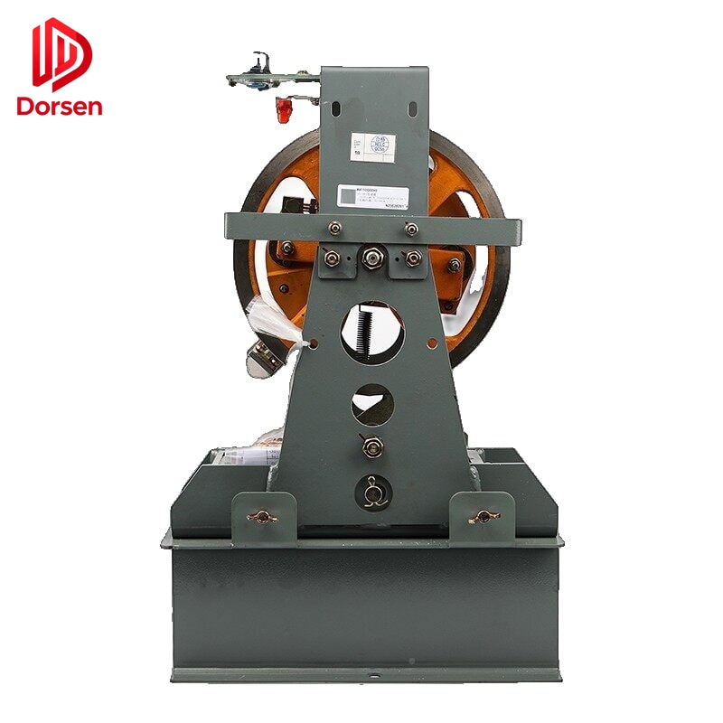
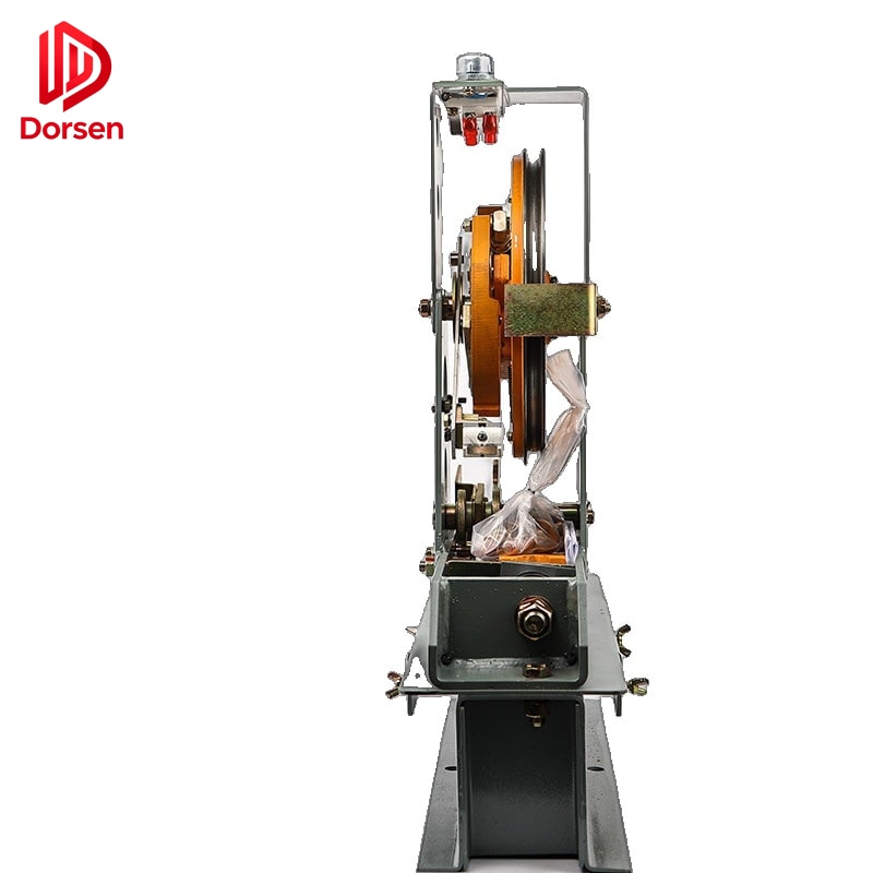
Overspeed governor (detects) → Governor rope (transmits) → Safety gear (brakes) → Guide rails (surface)When the speed governor detects overspeed, it grips the governor rope, creating tension that pulls the safety gear activation linkage. The safety gear jaw blocks engage the guide rails, converting the car’s kinetic energy into heat through controlled friction.
1.2 Progressive vs. Instantaneous: Working Principles
Instantaneous safety gear engages rapidly, clamping the guide rails with spring-assisted mechanical force. The braking event is abrupt — deceleration can reach levels that are unacceptable for passenger comfort and safety at higher speeds. Instantaneous gear is mechanically simpler and was standard on early low-speed elevators.
Progressive safety gear applies braking force gradually through spring-loaded wedges or eccentric rollers that slide along the guide rail working face. The controlled deceleration limits occupant impact forces to certified levels — typically ≤ 1.0 g (9.81 m/s²) for passenger elevators per EN 81-20.
| Aspect | Instantaneous | Progressive |
|---|---|---|
| Engagement mechanism | Rapid clamp on rails | Controlled sliding deceleration |
| Braking element | Hardened steel wedges | Eccentric rollers or spring-opposed wedges |
| Force application | Spring-assisted mechanical | Spring-loaded, self-energizing |
| Typical speed band | ≤ 0.63 m/s | 0.63 m/s to 10+ m/s |
| Occupant deceleration | Higher jerk (legacy) | Certified ≤ 1.0 g |
| Post-trip reset | Often manual | Manual per design |
| Current market use | Legacy low-speed only | All new passenger elevators > 0.63 m/s |
2. Speed-Based Selection Rules
2.1 Code-Aligned Speed Thresholds
International practice under EN 81-20 and ASME A17.1 divides applications as follows:
| Rated car speed | Safety gear type typically required |
|---|---|
| ≤ 0.63 m/s | Instantaneous gear may be permitted (jurisdiction-dependent) |
| 0.63 – 1.0 m/s | Progressive gear with controlled deceleration |
| > 1.0 m/s | Progressive gear with type-tested deceleration performance |
| 2.5 – 4.0 m/s | Progressive gear with enhanced deceleration certification |
| High-rise (> 4 m/s) | Dual progressive sets with independent actuation (project-specific) |
Instantaneous gear engages rapidly and is mechanically simpler, but it is not a universal substitute for progressive gear on faster units. Speed rating mismatch produces incorrect tripping behavior — a safety issue, not a performance preference.
2.2 Governor Tripping Speed Relationship
The overspeed governor tripping speed must align with the safety gear’s certified speed range:
| Parameter | Typical value | Source |
|---|---|---|
| Rated elevator speed | Machine nameplate | Car data plate |
| Governor tripping speed (down) | 115–140% of rated speed | Governor nameplate / code |
| Governor tripping speed (up) | 115% of rated speed | Governor nameplate / code |
| Tripping speed tolerance | ±3% | EN 81-20 testing requirement |
| Safety gear certified range | Must encompass tripping speed | Gear nameplate |
If the governor trips at a speed outside the safety gear’s certified range, the gear may not engage (under-speed trip) or may engage with excessive force (over-speed trip). Both conditions are safety hazards.
3. Safety Gear Type Classification
3.1 Detailed Type Comparison
| Type | Braking element | Force application | Max certified speed |
|---|---|---|---|
| Wedge-type (instantaneous) | Hardened steel wedges | Spring-assisted mechanical | ≤ 0.63 m/s (legacy) |
| Eccentric roller (progressive) | Eccentric rollers + springs | Spring-loaded, self-energizing | Up to 3.0 m/s |
| Wedge-type (progressive) | Spring-opposed wedges | Hydraulic damping + springs | Up to 10.0 m/s |
| Multiple wedge (high-speed) | Distributed wedge array | Hydraulic or spring | Up to 10.0+ m/s |
3.2 Directionality
| Configuration | Application | Notes |
|---|---|---|
| Unidirectional (down only) | Standard passenger car side | Most common configuration |
| Bidirectional | Specific designs requiring up-direction braking | Less common; verify nameplate |
| Counterweight side | Separate gear on counterweight frame | Independent specification required |
Confirm directionality matches the installation side and system design before ordering.
4. Four Label Checks Before You Buy
Progressive gear manuals from multiple manufacturers (including Can-Lift, Sky, and international OEM assemblies) use the same verification sequence:
4.1 Directionality
Confirm unidirectional (down only) vs. bidirectional matches the car side and system design. Installing a unidirectional gear on the wrong side produces no braking action during an overspeed event.
4.2 Nominal Speed vs. Tripping Speed
Rated elevator speed and governor tripping speed must fall within the gear’s certified range. The nameplate lists minimum and maximum tripping speeds — not just rated elevator speed. Mismatch leads to stopping forces outside design limits.
4.3 Total Mass (P + Q)
Car empty weight (P) plus rated load (Q) must sit inside the nameplate capacity table for that speed and rail type. Tables differ for:
- Machined rails (Type B) — tighter tolerances, higher capacity rating
- Cold-drawn rails (Type A) — standard capacity rating
Using the wrong table row is a certification violation even if the gear physically fits.
4.4 Guide Rail Compatibility
Verify all of the following against the nameplate:
| Parameter | Common values | Critical? |
|---|---|---|
| Rail model | T75, T89, T127, T140 | Yes — jaw profile match |
| Rail thickness | 9, 10, 14, 16 mm | Yes — jaw opening dimension |
| Rail production type | A = cold-drawn / B = machined | Yes — separate capacity tables |
| Lubrication condition | Oiled vs. dry rail rating | Yes — affects friction coefficient |
| Jaw block profile | Must match rail working face | Yes — engagement geometry |
Do not install on rail types not listed on the label.
5. Load Capacity and Jaw Block Configuration
5.1 Block Count vs. Load
General industry guidance linked to total suspended mass (P + Q):
| Approximate load range | Typical block configuration |
|---|---|
| Up to ~1,000 kg | 2 blocks |
| ~1,000 – 2,500 kg | 4 blocks |
| ~2,500 – 4,000 kg | 6 blocks |
| Above ~4,000 kg | 6–8 blocks distributed on frame |
Exact counts are always nameplate-driven — use tables only as orientation, not as a substitute for the original model data.
5.2 Mounting and Frame Considerations
| Factor | Specification source | Notes |
|---|---|---|
| Ear spacing (center distance) | Manufacturer drawing | Must match existing bracket |
| Pin hole diameter and position | Manufacturer drawing | Linkage rod compatibility |
| Floor bracket type | Project design | May require new brackets with gear change |
| Clearance to car frame | Shaft layout drawing | Verify before ordering larger gear |
Field modification of safety gear brackets or frames is not acceptable under any code jurisdiction.
6. Safety Gear Testing Requirements
6.1 Type Certification Testing
EN 81-20 mandates a full safety gear test with rated load at tripping speed during type certification. The test verifies:
- Engagement at tripping speed within certified range
- Deceleration rate within occupant safety limits
- No guide rail damage beyond permitted limits
- Reset mechanism functions correctly after trip
6.2 Field Testing Schedule
| Test | Frequency | Requirement |
|---|---|---|
| Governor tripping speed verification | Annual (passenger) / 6 months (heavy freight) | ±3% of rated tripping speed |
| Safety gear test (empty car) | Annual | Car arrested without excessive rail damage |
| Guide rail inspection after test | After every test | Scoring and deformation at jaw contact points |
| Linkage and rope inspection | Annual | Wear on pins, rods, governor rope |
| Nameplate legibility | Every inspection | Must remain readable |
6.3 Test Procedure Summary
Step 1: Verify governor tripping speed before safety gear test
Step 2: Run car downward at inspection speed
Step 3: Trigger governor manually or by controlled overspeed
Step 4: Measure stopping distance and deceleration rate
Step 5: Inspect guide rails at jaw contact points for damage
Step 6: Dismantle and inspect safety gear for wear
Step 7: Reset safety gear and verify normal operation
Step 8: Document test results in maintenance log
After testing, guide rails at the safety gear contact points must be inspected for deformation or scoring. Rail replacement may be required before returning to service.
7. Common Compatibility Failures
Field-verified patterns from multiple service databases:
| Failure | Symptom | Prevention |
|---|---|---|
| Jaw block vs. rail profile mismatch | Abnormal braking, noise, incomplete engagement | Match rail type A/B exactly |
| Speed class mismatch | Governor trips outside calibrated range | Cross-reference tripping speed |
| Mounting dimension deviation | Cannot fit without bracket modification | Request dimensional drawing first |
| Missing linkage parts | Cannot connect governor rope after delivery | Include complete BOM in quote |
| Wrong directionality | No braking on overspeed event | Confirm car side and gear direction |
8. Related Parts to Include in Project Scope
A safety gear quote request should specify whether these are needed:
| Component | When to include |
|---|---|
| Overspeed governor | Speed class change or governor at end of life |
| Governor rope | Worn, wrong diameter, or wrong length |
| Linkage rods and pins | Bent, worn, or missing after trip |
| Reset mechanism components | Damaged during test or trip event |
| Floor brackets | Corroded or incompatible with new gear frame |
| Guide rail sections | Scored from previous trip or test |
| CE or type-examination documents | All export markets |
9. Recommended Procurement Flow
Read original nameplate → Confirm speed + P+Q + rail type + side
→ Cross-check capacity table → Request certification documents
→ Verify linkage and governor compatibility → Quote
→ Technical review → Order → Pre-installation dimensional check
Send a clear photo of the existing safety gear label. Model similarity across brands does not imply interchangeability.
10. Emerging Considerations
10.1 Electronic Governors and Safety Gear Interaction
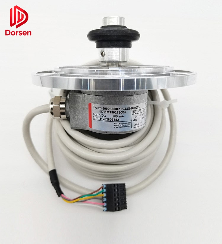
Electronic governors using shaft encoders and dedicated processors provide precise velocity monitoring including jerk detection. When replacing safety gear on systems with electronic governors, verify that the governor tripping speed calibration remains within the new gear’s certified range after any controller software updates.
10.2 MRL Installations
Machine-room-less elevators mount the governor in the shaft overhead with limited access. Safety gear replacement in MRL shafts requires planning for disassembly sequence and may need additional linkage components due to compact governor placement.
DORSEN supplies OEM-compatible safety gear with export documentation support. On safety-critical components, specification confirmation before payment is not bureaucracy — it is part of the safety system.