

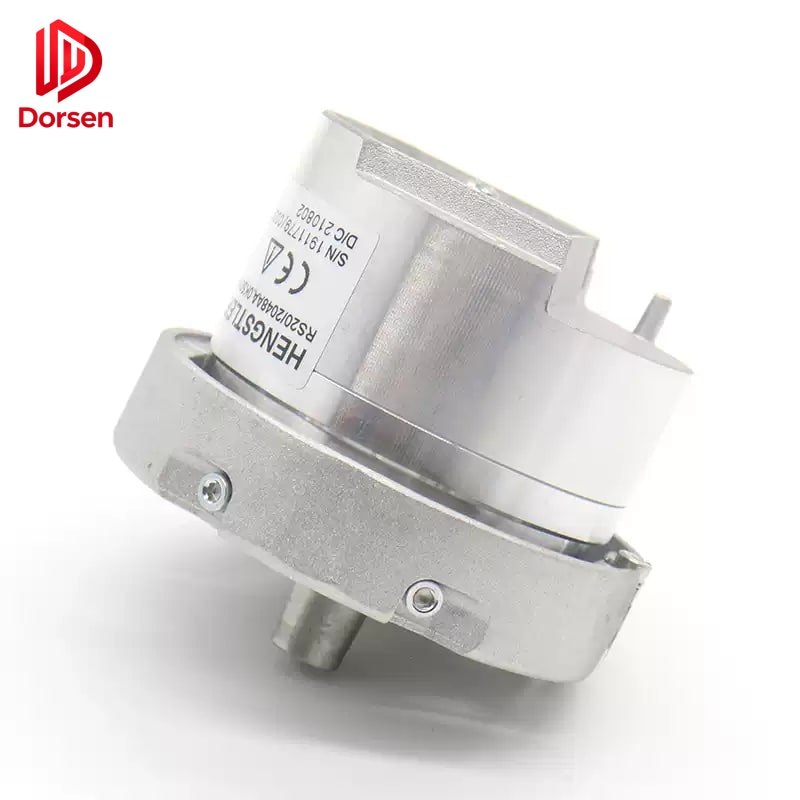
A drive fault labeled “encoder error” does not always mean the encoder itself has failed. Across multiple field maintenance case studies, a large share of leveling and speed feedback problems trace back to wiring, shielding, mechanical slip, or leveling hardware — not a defective feedback unit.
This guide provides a comprehensive troubleshooting sequence covering symptom classification, leveling hardware verification, shaft data comparison methods, electrical and shielding diagnostics, traction slip testing, replacement decision criteria, and post-replacement commissioning requirements.
1. Understanding Encoder Feedback in Elevator Drives
1.1 How Feedback Controls Speed and Position
The encoder converts motor shaft rotation into electrical signals. The inverter uses these signals to:
- Regulate motor speed against the commanded velocity profile
- Count pulses for floor positioning between deceleration points
- Detect direction of rotation for safety monitoring
- Provide closed-loop control for permanent-magnet synchronous motors (via Sin/Cos analog signals)
Any disruption in the feedback signal — whether from a failed encoder, damaged cable, electrical noise, or mechanical slip at the traction sheave — produces symptoms that the controller reports as “encoder fault.”
1.2 Feedback Types and Vulnerability
| Type | Signal format | Primary vulnerability |
|---|---|---|
| Incremental (A/B/Z) | Square-wave pulses | Cable break, connector oxidation, noise on pulse lines |
| Sin/Cos (analog) | Sine/cosine waveforms | Shield failure, ground loop, low signal amplitude |
| Absolute | Serial position word | Communication protocol error, battery failure |
| Tachometer (legacy) | DC voltage | Brush wear, carbon dust, voltage drift |
Sin/Cos systems on permanent-magnet machines are particularly sensitive to electrical noise because the signal amplitude is low (typically 1 Vpp). A small amount of interference can corrupt position calculation without triggering an obvious cable fault.
2. Symptom Classification
2.1 Symptom-to-Cause Matrix
Start with symptoms, not the part number:
| What the crew sees | Likely category | First action |
|---|---|---|
| Random mis-leveling (different offset each trip) | Signal interference or rope slip | Compare two shaft-learn runs |
| Fixed offset at every floor | Leveling sensor or magnetic plate shift | Inspect U/V/W plates and sensors |
| Jitter only in express run | Loose coupling or worn disc | Check mechanical coupling torque |
| Fault appears after maintenance | Wiring or connector issue | Re-inspect terminations and routing |
| Gradual drift over weeks | Rope slip or coupling loosening | Chalk mark slip test |
| Fault only in one direction | Damaged channel or partial cable break | Swap A/B channels to test |
| No fault in inspection, fault in automatic | Parameter or speed-dependent issue | Compare inspection vs. auto parameters |
2.2 Fault Code Interpretation
| Drive fault code (generic) | May indicate | Confirm with |
|---|---|---|
| Encoder error / feedback loss | No pulses detected | Pulse measurement at drive terminals |
| Position error / overshoot | Cumulative count mismatch | Two-pass shaft learn comparison |
| Speed feedback fault | Erratic speed signal | Oscilloscope or drive diagnostic screen |
| Sin/Cos imbalance | Analog channel mismatch | Voltage measurement per channel |
| Direction fault | A/B channel reversed or missing | Channel swap test |
Fault codes identify the symptom category — not the root cause. Always perform mechanical and electrical checks before ordering a replacement encoder.
3. Step 1: Rule Out Leveling Hardware
3.1 Leveling System Components
Before blaming the encoder, confirm the leveling subsystem:
| Component | Location | Failure symptom |
|---|---|---|
| Floor magnetic plates | Each landing door jamb | Fixed offset at one floor |
| Leveling sensors (U/V/W) | Car top | Offset at multiple floors |
| Deceleration switches | Car top | Overrun or undershoot at floors |
| Leveling cam or tape | Governor or car top | Position reference drift |
3.2 Leveling Hardware Checks
| Check | Method | Pass criteria |
|---|---|---|
| Magnetic plate security | Visual and push test | Plates firmly mounted, no shift from vibration |
| Sensor alignment | Gap measurement | Per manufacturer spec (typically 5–15 mm) |
| Sensor cleanliness | Visual inspection | No metal dust, oil, or debris on sensor face |
| Deceleration switch count | Controller parameter vs. physical count | Match exactly |
| Plate polarity | Manufacturer marking | Correct orientation for sensor type |
Mis-leveling concentrated on one floor often points to a local plate or sensor problem rather than encoder feedback failure. If only floor 7 is off by 10 mm and all other floors are within tolerance, inspect floor 7’s magnetic plate before the encoder.
4. Step 2: Two-Pass Shaft Data Comparison
4.1 Procedure
A widely used field method for ruling out encoder interference or rope slip:
- Complete a shaft learn (or position teach) and record floor position data
- Repeat the procedure without changing any mechanical settings
- Compare corresponding floor values between the two runs
- Note the maximum difference at any floor
4.2 Interpretation
| Result | Diagnosis | Next action |
|---|---|---|
| Difference ≤ 3 mm at all floors | Encoder signal stable | Investigate leveling hardware or drive parameters |
| Difference > 3 mm at one or more floors | Encoder signal quality or rope slip suspect | Proceed to electrical checks AND chalk slip test |
| Difference increases on upper floors | Rope stretch or slip accumulating with travel | Traction slip test priority |
| Difference random between runs | Electrical noise or intermittent connection | Shielding and connector inspection |
Practical threshold: If the difference at any floor exceeds 3 mm, treat encoder signal quality or traction slip as suspect before replacing the encoder.
This check is especially important on permanent-magnet systems using Sin/Cos feedback, where small analog signals are more vulnerable to electrical noise than digital pulse systems.
5. Step 3: Electrical and Shielding Checks
5.1 Common Correctable Causes
Maintenance teams consistently report these as the most common correctable causes of encoder faults:
| Cause | Frequency | Fix |
|---|---|---|
| Encoder cable routed with power wiring | Very common | Separate routing, minimum 100 mm distance |
| Shield drain not terminated at drive end | Very common | Terminate per drive manufacturer scheme |
| Motor ground strap missing or broken | Common | Install or replace ground strap |
| Oxidized connector pins after humidity | Common | Clean or replace connector |
| Coupling slip between encoder hub and shaft | Common | Re-torque or replace coupling |
| Cable damaged by rubbing on bracket | Moderate | Reroute and replace damaged section |
| Wrong encoder voltage supply | Moderate | Verify 5V vs. 12V on nameplate |
5.2 Sin/Cos Reference Check
On inspection run, measure Sin and Cos channel voltages against signal ground:
| Parameter | Expected value | Action if out of range |
|---|---|---|
| Sin channel voltage | 1.45–1.55 V | Check cable and encoder head |
| Cos channel voltage | 1.45–1.55 V | Check cable and encoder head |
| Channel balance | < 0.05 V difference | Imbalance indicates encoder or cable fault |
| Signal amplitude (peak-to-peak) | ~1.0 Vpp | Low amplitude suggests cable attenuation |
Large deviation from expected values suggests cable damage, connector oxidation, or encoder head failure — but verify cable first before ordering a new encoder.
5.3 Shielding Best Practices
| Practice | Detail |
|---|---|
| Cable routing | Encoder cable in separate tray from power, brake resistor, and lighting |
| Shield termination | Drain wire connected at drive end per manufacturer diagram |
| Ground loop prevention | Single-point ground reference — avoid grounding shield at both ends unless specified |
| Connector quality | Use original or OEM-specified connector — no bare wire splices |
| Cable support | Secure cable to prevent rubbing against moving parts or sharp edges |
6. Step 4: Traction Slip Test
6.1 Why Slip Mimics Encoder Failure
Encoder feedback assumes the rope does not slip on the sheave. The encoder accurately reports sheave rotation — but if the rope slips, sheave rotation no longer equals car travel. The controller sees this as position error and may log an encoder fault.
Rope slip is caused by unequal rope tension, worn sheave grooves, or insufficient traction under load. It is one of the most overlooked causes of encoder-related callbacks.
6.2 Chalk Mark Test Procedure
- Mark the rope against the sheave at one floor landing with chalk or tape
- Run the car one full floor up and return to the starting floor
- Measure mark drift on the sheave relative to the rope
- Repeat with 50% rated load in the car
| Result | Interpretation | Action |
|---|---|---|
| Drift < 5 mm (empty and loaded) | Traction adequate | Focus on electrical diagnostics |
| Drift 5–15 mm | Moderate slip | Measure rope tension — equalize to within 10% |
| Drift > 15 mm | Significant slip | Rope tension, groove wear, possible sheave replacement |
| Drift only under load | Load-dependent slip | Tension imbalance worsens under load — priority tension check |
Field acceptance used by many crews: single-floor slip under 5 mm on both empty and loaded runs.
6.3 Rope Tension Connection
If slip is confirmed, measure rope tension on all ropes in the set. ASME A17.1 requires the lowest tension to be within 10% of the highest. Unequal tension is the dominant preventable cause of traction slip. See our companion article on rope tension and position feedback for the complete equalization workflow.
7. Step 5: Replacement Decision Criteria
7.1 When Replacement Is Justified
| Condition | Verification | Confidence |
|---|---|---|
| Pulse output absent with confirmed good wiring | Oscilloscope at drive input | High — encoder failure |
| Physical wear, scoring, or grinding noise | Visual and auditory inspection | High — mechanical failure |
| Repeated direction or resolution faults after recalibration | Multiple calibration attempts failed | High — encoder or coupling |
| Service life beyond 5–8 years with intermittent signal loss | Age + symptom pattern | Moderate — plan replacement |
| Sin/Cos channels permanently imbalanced after cable verified | Voltage test with known-good cable | High — encoder head failure |
| Drive upgrade requiring different feedback type | Engineering specification | Required — not optional |
7.2 When Replacement Is NOT Justified
| Condition | Correct action instead |
|---|---|
| Slip test shows > 5 mm drift | Equalize rope tension, inspect sheave grooves |
| Shield not terminated | Terminate shield per drive manual |
| One floor mis-leveled only | Inspect magnetic plate and leveling sensor at that floor |
| Fault only after maintenance | Re-check wiring against original photograph |
| Sin/Cos imbalance with damaged cable | Replace cable first, then re-test |
8. After Replacement: Commissioning Requirements
Even a correctly matched OEM-compatible encoder can cause faults if commissioning is skipped:
| Step | Action | Purpose |
|---|---|---|
| 1 | Lock out and verify zero voltage | Safety |
| 2 | Photograph and replicate original wire routing and shield termination | Prevent wiring errors |
| 3 | Verify encoder supply voltage at terminals | Confirm wiring before motion |
| 4 | Perform zero calibration and direction verification | Align electrical zero to mechanical reference |
| 5 | Run shaft learn if controller requires it | Rebuild floor position table |
| 6 | Two-pass shaft learn comparison | Verify ≤ 3 mm repeatability |
| 7 | Test express and inspection modes at every floor | Confirm resolution and position accuracy |
| 8 | Run loaded test (50% capacity minimum) | Reveal slip-related errors invisible at empty car |
Acceptance criterion: floor leveling within ±5 mm at every landing, with two consecutive shaft-learn runs differing by less than 3 mm per floor.
9. Information That Speeds Up Your Quote
If replacement is confirmed after completing the diagnostic sequence, send:
| Information | Why needed |
|---|---|
| Encoder nameplate photo | Resolution, voltage, connector type, model |
| Inverter or drive model | Parameter compatibility |
| Elevator brand and controller type | Mounting and connector family |
| Fault history | When started, empty vs. loaded, intermittent vs. permanent |
| Diagnostic results summary | Confirms root cause analysis was performed |
| Quantity and destination | Lead time and export documentation |
10. Complete Diagnostic Workflow Summary
Receive "encoder fault" callback
  → Step 1: Check leveling hardware (plates, sensors, switches)
  → Step 2: Two-pass shaft learn comparison (3 mm threshold)
  → Step 3: Electrical checks (shielding, connectors, Sin/Cos voltage)
  → Step 4: Traction slip test (chalk mark, 5 mm threshold)
  → Step 5: Decision — replace encoder OR fix root cause
  → If replacing: Commission with full test sequence
  → Document findings in maintenance log
DORSEN supplies OEM-compatible encoders with specification verification before shipment. Wrong-part returns cost more than one extra hour of diagnostics — confirm the root cause first, then match the part.